


HTC M8 Battery Replacement

Send this link via e-mail
|
Tweet |
|

Step 1 - Before You Start
Before you start with the repair, discharge the battery below 25%.
A charged Li-Ion battery can catch fire and explode if punctured.
Caution:
If the battery is swollen, take adequate measures and precautions.
Do not heat your phone. You can use isopropyl alcohol around the edges of the back cover to weaken the adhesive.
Wear eye and hand protection when working with swollen batteries.


Step 2 - SIM Card
Back to top
Turn off your device.
You can use a paperclip or a SIM card eject tool.
Insert the tool into the pin hole in the SIM card tray, located on the upper left hand side of the phone.
Press to eject the tray.
Remove the SIM card tray assembly from the HTC One M8.
Note:
Popping-out the sim tray may require a significant amount of force.
When reinserting the SIM card, ensure that it is in the proper orientation relative to the tray.


Step 3 - Speaker Grills
Back to top
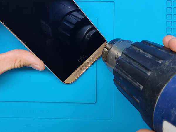
Use a heat gun or a hair dryer around the edges of the phone for about a minute in order to soften up the adhesive underneath.
Use a plastic spudger or a thin metal opening tool to gently peel up the lower speaker grille.
Remove the top speaker grille the same way.
Note:
The adhesive residue can be messy when removed, you can clean it with isopropyl alcohol.

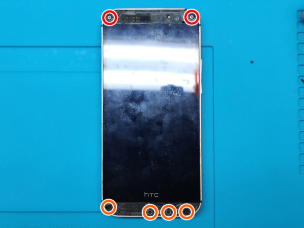
Step 4 - Screws
Back to top
Remove the two silver 3mm Phillips #00 screws from the top.
Remove the four black 4mm T5 Torx screws from the bottom.


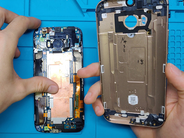
Step 5 - Display
Back to top
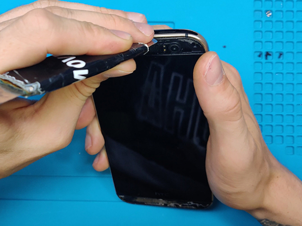
Work your way around the perimeter of the phone with a spudger to free the clips that secure the rear case to the display assembly.
Once you have successfully unclipped the display assembly, separate it from the chassis.
Note:
A metal spudger is used, but a nylon spudger is a better option to prevent marring the device.
Be careful not to lose the power button: it sits loosely in the top of the lower chassis.
Attention:
Significant force may be required to pry the casing apart.
5.1 - Motherboard
Remove the two silver 2 mm Phillips #00 screws securing the battery connector to the motherboard.
Use a plastic opening tool to gently pry up the battery connector.
Use the point of a spudger to lift the battery connector out of its socket on the logic board.
Connect the new battery to the motherboard and turn on the device to test it.
After a successfull test, unplug the battery to continue with the repair.


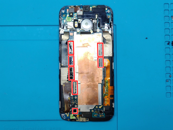
Step 6 - Unplugging
Back to top
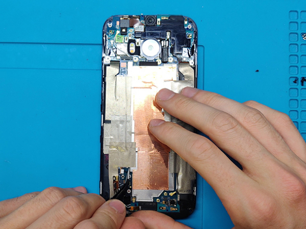
Connectors and parts of the board are covered with protective foils.
To reach the connectors, remove all the foils.
Use the tip of a spudger to disconnect the seven ZIF connectors.
Use a pair of tweezers to gently pull the seven ribbon cables free of the connectors.
Use a spudger or a pair of tweezers to disconnect the two (four) antenna cables.


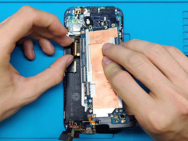
Step 7 - Removing The Motherboard
Back to top
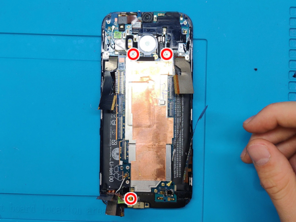
Remove three silver 3mm screws using T5 screwdriver.
Use a plastic opening tool to gently pry the motherboard free of the display assembly.
Tip:
Use a heat gun to loosen up the glue holding the motherboard to the display assembly.
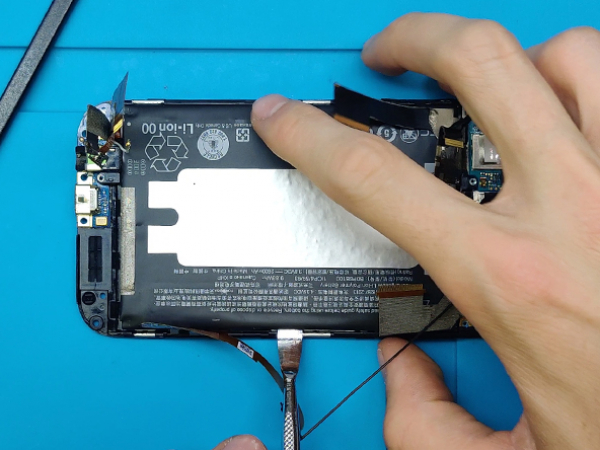


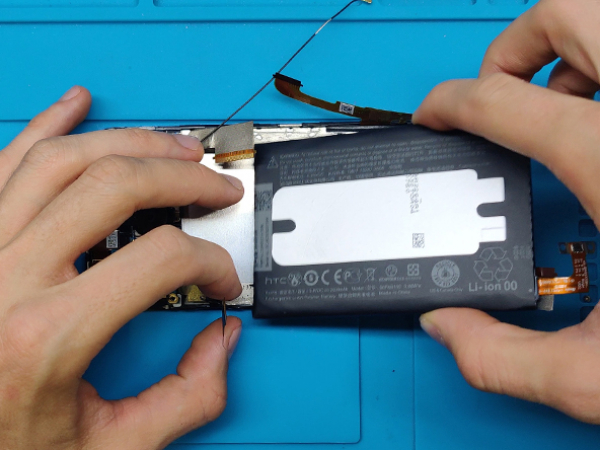
Step 8 - Removing The Battery
Back to top
Gently bend ribbon cables out of the way of the battery.
Use a spudger or a plastic opening tool to gently pry up the battery from the display assembly.
Tip:
Use a hair dryer or a heat gun to loosen up the adhesive securing the battery to the display assembly.


Step 9 - Installing The New Battery
Back to top
Place the new battery in the display assembly.
Be carefull about the ribbon cables.
There is enough of the old adhesive left in on the assembly so you don't need to add more.


Step 10 - The Return Of The Board
Back to top
From this point just reverse first 6 steps.
Carefully reinstall the board.
Secure the board with three silver 3mm screws.


Step 11 - Reconnect
Back to top
Replug all the ribbon cables, ZIF connectors and antennas.
Leave the battery connector for the grand finale.
Install two silver 2mm Phillips #00 screws to secure the battery connector to the motherboard.


Step 12 - Reassemble I
Back to top
Now, put the display assembly in the rear case.
Start with the top part.
Then start pressing arround the perimeter of the screen.
All the clips should pop-in to secure the screen assembly.


Step 13 - Reassemble II
Back to top
Secure the four black 4mm T5 Torx screws to the bottom side.
Secure the two silver 3mm Phillips #00 screws to the top side.
Install the bottom and the top speaker grills.
Note:
There is enough of the old adhesive left on the speaker grills, so they should stick tight.