


Samsung Galaxy S20 Screen Replacement

Send this link via e-mail
|
Tweet |
|


Step 1 - Warm Up The Back Glass
Turn off your Samsung Galaxy S20.
Remove the SIM tray.
Apply heat to the back of the phone to soften the adhesive which holds the back glass.
We are using a special heating plate (not shown in photos/video)
You can use a heat gun or a hairdryer for a minute or so at max. 110°C.
You may need to repeat the process because the glue hardens quickly.
Note:
Opening your Samsung Galaxy S20 will damage the waterproof sealing on your device.
Your phone will still function normally if you do not replace the adhesive seals, but it will lose its water ingress protection.
Caution:
Take care and avoid overheating your Samsung S20.
Both the AMOLED display and the battery can be damaged by excessive heat.


Step 2 - Removing The Back Glass
Back to top
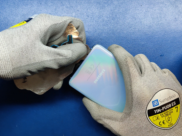
Insert the thin metal opening tool (iFlex) between the back glass and the metal frame.
Start from the bottom and work your way around the edges of the phone.
We are using some isopropyl alcohol as a glue solvent.
Avoid the area around volume and power buttons.
There is nothing attached to the back glass, so you can now remove it.
Caution:
The edge of the back glass near the buttons is recessed to fit the metal frame of the phone.
Avoid this area when cutting through the glue with the iFlex tool, since the glass is fragile in areas with curves and cutouts.


Step 3 - Removing The Charging Coil
Back to top
Remove the five 4.0mm Phillips screws securing the Qi charging coil.
The bottom part of the coil is secured with some glue on the speaker.
It should come off easily, just like a sticker.
Then remove the charging coil completely.


Step 4 - Disconnecting The Battery & Other Connectors
Back to top
Removing the charging coil gave us access to the battery connector and other connectors as well.
As always, you should disconnect the battery first.
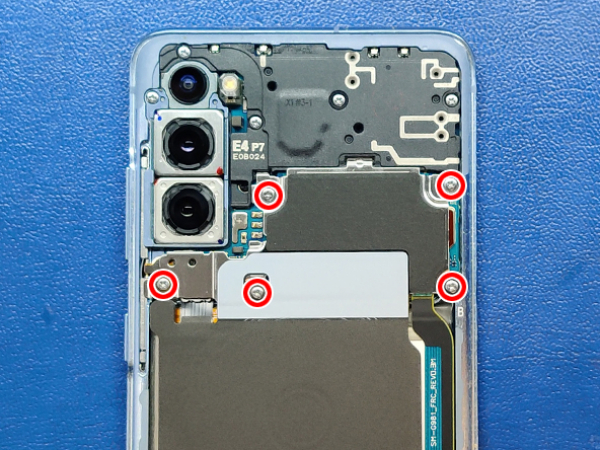
Remove the four 4.0mm Phillips screws securing the mainboard cover.
Remove the plastic MAIN board cover/shield.
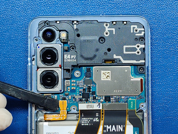
Now disconnect all the connectors from the mainboard.
Lever carefully and bend contacts slightly to the side.
Caution:
When you pry to disconnect the connectors on the board, avoid levering on places where there are small components on the board so as not to damage them.


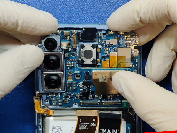
Step 5 - Removing The MAIN Board
Back to top
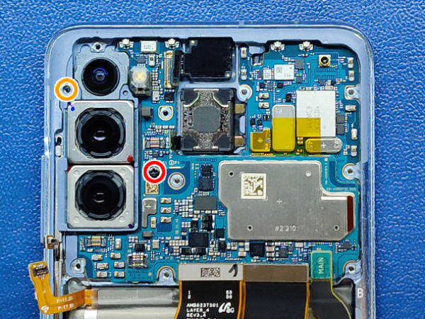
Remove the screws holding the mainboard and the cameras.
1x 2.8mm Phillips screw
1x 4.0mm Phillips screw
Now lift the board carefully on one side and take it out with both hands.
Make sure no cables or connectors get caught.
Avoid touching the camera lenses.
Caution:
Take special care when handling the mainboard.
Soldered components are fragile and hard to repair.


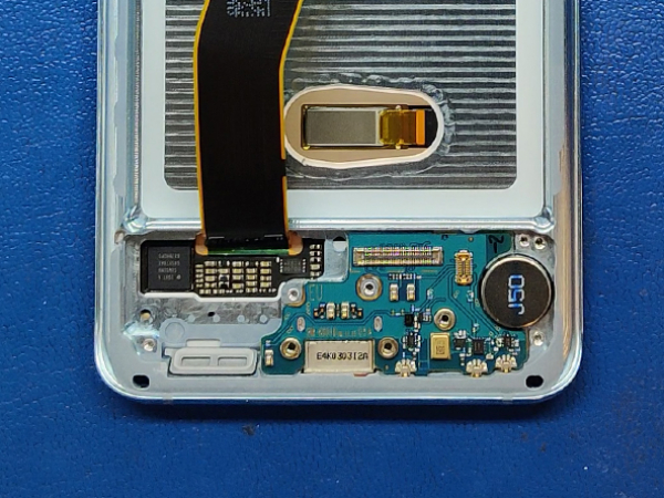
Step 6 - Removing The Speaker And The SUB Board
Back to top
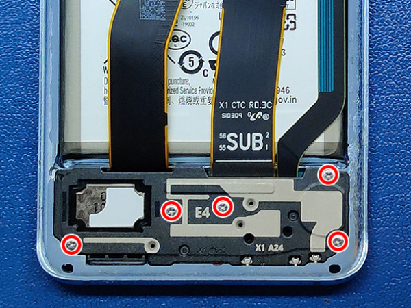
Loosen the screws securing the plastic cover and the embedded speaker.
5x 4.0mm Phillips screws.
Lift the speaker and take it out.
Remove the three 4.0mm Phillips screws securing the board with the USB-C charging socket.
Detach the connectors from the bottom board with the tip of a spudger.
Remove the two cables on the right side.
The cable with a noticeable curve to the right is permanently attached to the display.
Lift the SUB board from the side facing the battery.
Pull the board upwards to remove it from the phone housing.


Step 7 - Removing The Battery
Back to top
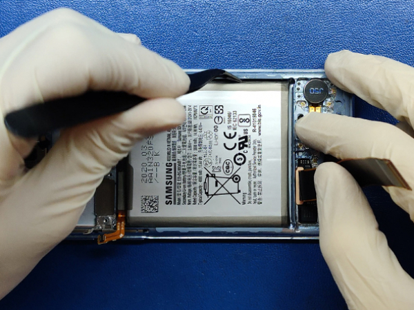
The battery is heavily glued to the phone housing.
We are using a bit of isopropyl alcohol to dissolve the glue and the hot plate to loosen it.
You can once again use the heat gun or the hairdryer.
Do not heat-up the battery directly, apply heat from the display side.
Then pry the battery out carefully.
Caution:
It is advised to use plastic tools when working with a battery.
Do not by any means puncture the battery, especially with a metal tool, since the battery can catch fire and explode.
Also avoid bending and deforming the battery.


Step 8 - The New Display
Back to top
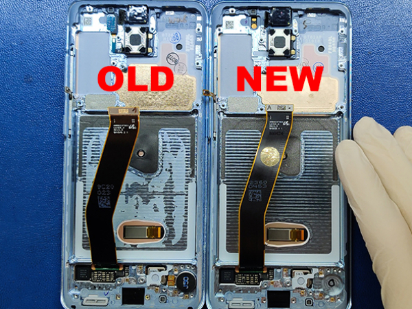
The replacement LCD comes together with the metal frame, under-display fingerprint scanner, and side buttons.
Only two things are missing, the vibration motor and the proximity sensor.
Some replacement parts can also miss the earpiece.
Ours has one already installed.
The vibra motor and the proximity sensor should be transfered from the old assembly.
Pry out the vibration motor from the old assembly and transfer it to the new one.
Now remove the proximity sensor and insert it in the new LCD assembly.
Press it slightly until it is properly seated.
Note I:
The vibration motor is held by a double-sided adhesive sticker.
It usually comes off with the vibra motor. If not, pry it off and stick it to the new LCD assembly before installing the vibration motor.
Note II:
The flex cable of the proximity sensor is secured to the phone housing with some glue.
Use a steel spatula or straight round tip tweezers to carefully pry the cable off the housing and remove it from the cavity.


Step 9 - Reinstalling The SUB Board, The Battery, And The Speaker
Back to top
Place the board with the USB socket at an angle at the bottom of the new LCD assembly.
Slide into the frame and make sure it is properly seated before you screw it on.
We are using 3mm double-sided adhesive tape to secure the battery.
Carefully remove the old glue from the battery before inserting it into the phone housing.
Now reconnect the two cables you previously disconnected from the sub-board.
The cables are properly marked with SUB and MAIN so you know which is connected to which board.
Secure the SUB board with 3x 4.0mm Phillips screws.
Now insert the speaker assembly bottom part first, and press it to click in place.
Secure the speaker assembly with five 4.0mm Phillips screws.


Step 10 - Reinstalling The MAIN Board And The Charging Coil
Back to top
Bend all connectors to the side before inserting the MAIN board.
Carefully put the MAIN board in place and be careful not to pinch any cables under the board.
When the MAIN board is flush and flat into the housing, you can screw it down.
1x 3.4.0mm Phillips screw
Reconnect all the flat cables and connectors like the front camera, proximity sensor, LCD flex cable, charging flex cable, buttons.
At the end reconnect the battery.
Now put the plastic shield in place, on top of the motherboard and secure it with a 1x 4.0mm screw so it doesn't move.
Insert and connect the wireless charging coil assembly.
Secure the wireless charging coil with six 4.0mm screws.
And secure the MAIN board and the plastic shield with the 3 remaining 4.0mm screws.
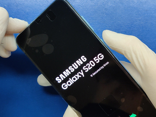


Step 11 - Reinstalling The Back Cover
Back to top
Before we secure the back cover to the metal frame, we will switch on the device.
If the device works as it should, we can now install the back cover.
Our back cover still has the original glue on it, so we will not add any glue or adhesive tape this time.
We will warm it up on the hot plate and then put it in place.
We are using a few clamp clips to hold the cover tight until the glue hardens.
And that is the end of this repair.