


Samsung Galaxy S8+ Screen Replacement

Send this link via e-mail
|
Tweet |
|


Step 1 - BEFORE YOU START
- Discharge the battery to under 25% before you begin disassembling the phone. - Turn off your phone. - Remove the SIM tray.
Caution:
- If the battery is swollen: - Take the necessary precautions and steps, - Avoid heating up your phone. - Use hand and eye protection.
Tip:
- If the display glass is shattered, tape over the glass to prevent additional breakage. - Cover the display with overlapping strips of clear self-adhesive tape.


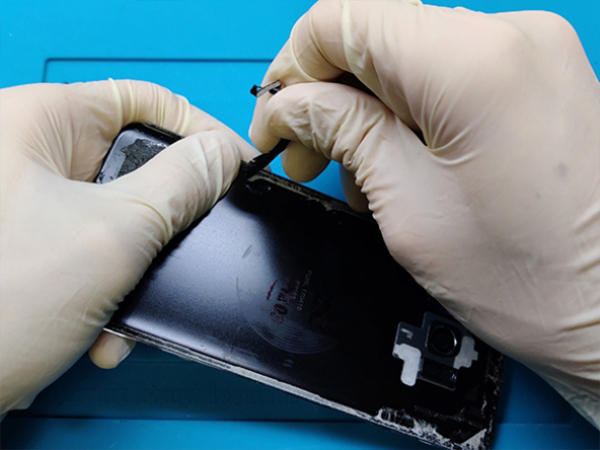
Step 2 - REMOVING THE BACK GLASS
Back to top
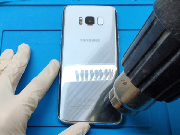
-Begin by heating the device's back with a hot. The rear cover is bonded using adhesive. -You might also use a hair dryer or a hot plate, but be careful not to overheat the phone—both the internal battery and OLED display are prone to heat damage. -Place the blade of the flat metal spudger between the back glass and the phone's casing. -Use the blade to carefully cut through the glue all the way around the edge of the back glass panel. -You might need to use the hot gun several times to reheat the back cover. since the glue sets up quickly. -You will be pushing the tool up rather than inserting it because of the curved glass. parallel to the phone's surface. -The phone is connected to the rear glass near the primary camera by the cable with the fingerprint sensor. -The cable should disengage as the rear glass is removed because it is quite short. -Look inside as you lift the glass to make sure the orange cable has a Blue connector is now unplugged. -Do not open the door if the fingerprint sensor cable seems snagged or remains taut. Call any longer. Before continuing, use the point of a spudger to disconnect the connector. -Take the phone's glass off. Note: To assist you in lifting the glass, try utilizing the suction cup.


Step 3 - NFC ANTENNA
Back to top
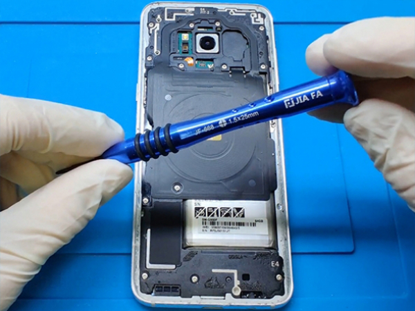
-Eleven 3.7 mm screws should be removed. -Remove the piece of plastic that is attached to the motherboard and covers the NFC. assembly of an antenna and a charging coil.


Step 4 - BATTERY CONNECTOR
Back to top
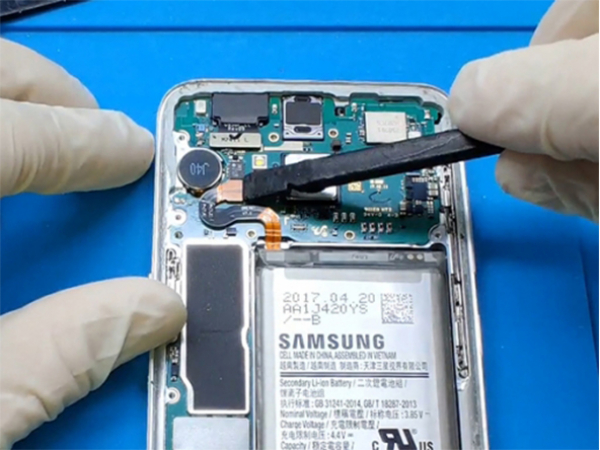
-As soon as you can during the repair procedure, detach the battery. -Disconnect the battery connector using the flat end of a spudger.


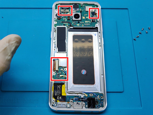
Step 5 - LCD CONNECTOR
Back to top
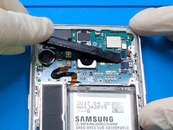
-Remove the connector for the sensor array using the flat end of the plastic spudger. -Unplug the connector for the front camera. -Remove the connector for the LCD digitizer.


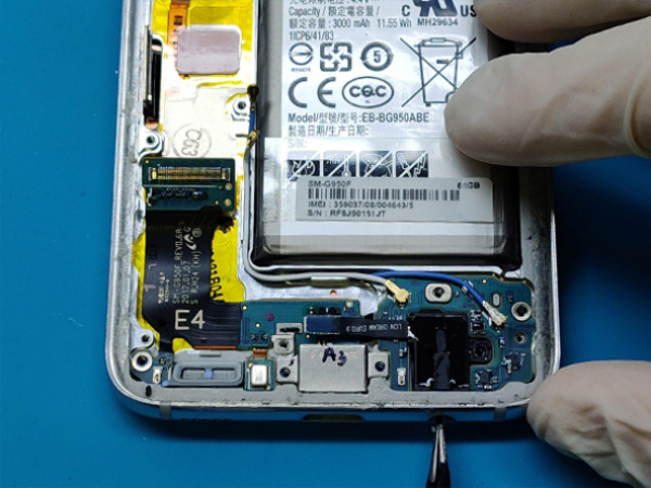
Step 6 - REMOVING THE MOTHERBOARD
Back to top
-Take off the plastic cover of the bottom daughter board. -Remove the daughter board's six 2.5mm screws. -Remove the connector from the headphone jack. -Unplug the antenna cable connections. -Gently raise the motherboard while keeping an eye on the nearby connectors. -Remove the motherboard from the device by cutting the cable connecting it to the daughterboard. -At this point, we'll take more components off the phone, like the front camera. -First, take out the front camera. -Use a plastic spudger or tweezers to delicately remove the front camera from the cavity. -Remove the front sensor array using the same procedure and tools. The vibration motor will then be revealed.


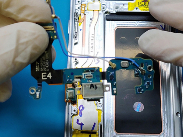
Step 7 - REMOVING THE DAUGHTER BOARD
Back to top
-Remove the headphone jack that was previously unplugged. -Remove the delicate antenna cables from the brackets with extreme care. You can now take out the daughterboard. -The daughter board's charging port and microphone are soldered to it.
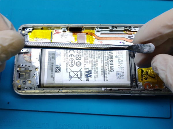


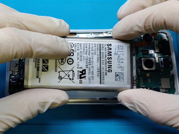
Step 8 - REMOVING THE BATTERY
Back to top
-Be careful when taking this step because there is a fire and explosive danger. -Use the spudger to lift the battery, being careful not to pierce or otherwise damage it. -Heating the battery to soften the glue is not advised. alternatively, use glue dissolving solution. -If a glue remover is not available, keep carefully prying the battery. -Once the battery has been successfully removed, thoroughly clean any glue residue off of it.


Step 9 - THE NEW SCREEN ASSEMBLY
Back to top
-At this point, all previously removed components should be transferred to the new screen assembly. -Verify that the new screen works properly by comparing the old and new LCD assemblies. will fit every component that we previously removed. Remove all of the new screen assembly's protective plastic foils. except from the one guarding the front glass. Note: We are using the assembly which contains the LCD and the middle frame.


Step 10 - INSTALLING THE DAUGHTER BOARD
Back to top
-Insert the daugther board into the newly assembled screen. -Align it with care so that the charging port glides into the middle frame's chamber. -Two antenna cables must be fastened to brackets. -Connect the flat cable to the daughter board after installing the headphone jack. -Now place the vibration motor in the button-shaped recess on the top of the frame. -The front sensor array should then be inserted into the cavity at the upper right as shown in the photograph. -The top left corner of the middle picture is where the front camera is located.


Step 11 - INSTALLING THE MOTHER BOARD
Back to top
-Link the daughterboard to the motherboard. -Put it softly into the frame now. -Pay close attention to the connections for the camera, sensors, and digitizer.
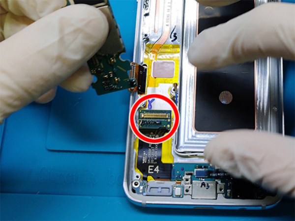
Step 12 - CONNECT ALL THE FLEX CABLE CONNECTORS
Back to top
-Connect the motherboard and the sensor array connector (top right). -Connect the motherboard's front camera connector (top left). -Connect the motherboard and the digitizer (bottom left). The antennas should then be connected to the motherboard.


Step 13 - INSTALLING THE BATTERY
Back to top
-To hold the battery in place, use the double-sided tape. -Place the battery within the frame and press firmly. - Connect it to the board that is close to the vibration motor. -Six screws that you previously removed are used to secure the daughter board. -Securely attach the black plastic cover to the daughterboard's top. -At this point, fasten the screw to the left middle piece. -Followed by the charging coil and NFC. -Ensure that everything fits well. -Put the final ten 3.7mm screws into place. Warning: The battery should always be connected last. Use only plastic tools to connect the battery.
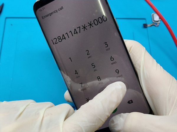
Step 14 - TESTING THE SCREEN
Back to top
-At this point, you should activate your phone to verify that everything is functioning properly.
-Before applying fresh adhesive and resealing the phone, always test your repair.


Step 15 - INSTALLING THE BACK COVER
Back to top
-If the existing rear cover is damaged, you can use a new one; otherwise, the old one will be reused. -You must clean the back cover of all adhesive residue and dirt if you plan to restore the original back cover. -By lightly heating the cover with the hot air gun, you can make things simpler. -Avoid using metal tools as they will harm the covering on the back cover. -Remove the fingerprint sensor from the rear cover because the heat gun has loosened the glue. -Place it there and attach it to the motherboard, which is in the cutout next to the back camera.
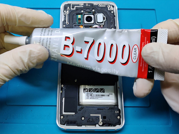


Step 16 - APPLYING THE GLUE
Back to top
-Put some B-7000 adhesive on the metal frame's edges. -The back cover should be placed on top of the frame. -To guarantee greater adhesion, use some clamps; after the glue has dried, remove them. Note: Be aware that your device lost its water ingress protection properties. Warning: Allow glue to dry for up to 48 hours, cure time increases with lower temperatures and decreases with higher temperatures. Information: B-7000 hardens by solvent evaporation and forms an immediate bond that is difficult to reposition after both adhesive-coated surfaces are placed in contact with each other and sufficient pressure is exerted to establish full contact.